Therefore, when using a reducer, the 15 degree/reduction ratio becomes the assembly error range for the keys of both shafts
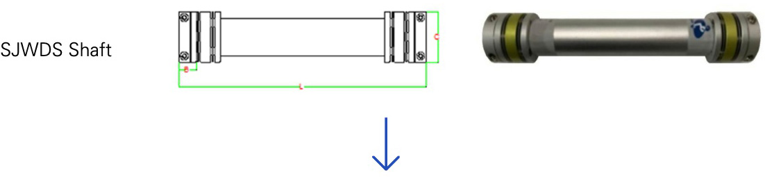
Feature
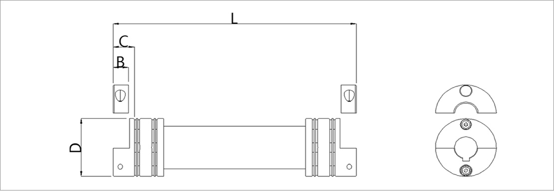
a Seperation type for coupling and pipe
b Existing ket seat
c Screwed with set screws at the end of the shaft
d Instal polyurethane sleeve
e occur twsting when assemble
Insert two couplings into the shaft at both ends. Complete to assemble by screwed bolts after drilling and tapping.
Feature
- Work on the assembly site
- If one axis is required on rotate due to the change in the position of the part receiving the load, it must be reassembled.
- Materials may need to be changed during production.
- Able to keep durable.
- Difficult to machine while mounted.
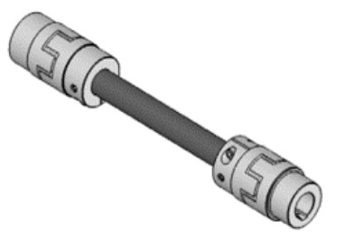
Feature
a Coupling and pipe with all-in-one design(machining)
b Screwed with using a bolt at the end of the shaft
c Installed polyurethane sleeve
(High torque performence, low misalignment-compared to the outside diameter)
d No keys
e No twisting when assemble
파이프와 커플링의 몸체를 CNC에서 필요한 길이마다 한번에 가공함
Feature
- Consume high cost and time
- No keyway to avoid reassemble.
- Occur slip due to tolerance if use only clamp excluding keyway.
- Difficult to machine while mounted.
![]()
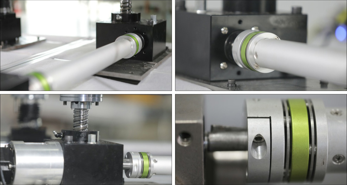
Simply assmeble in field · Avoid damage to the shaft end
Able to assemble in clean room
![]()
Remove slip · Increase durable
Increase safety
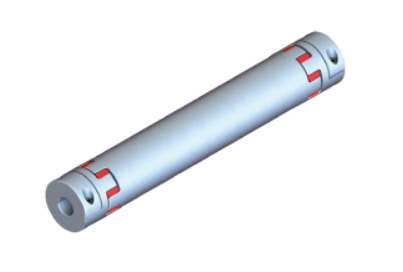
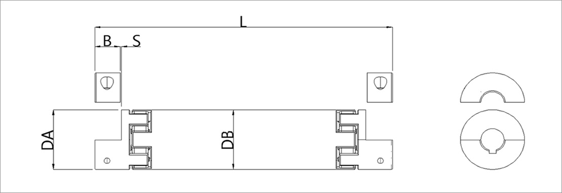
Feature
1 Coupling and pipe with all-in-one design
b Existing keyway
3 Screw bolts at the end of shaft(x2)
4 Install polyurethane sleeve
d occur torsion when assemble
Pipe attachment - Save cost and time
Able to supply by removing the clamp : Able to assemble in field by final assmeble without work.
Able to occured torsion : Twisted stiffiness cannot be avoided when each coupling keyway is inserted into the shaft at both ends.
- Removed Hub(Length of Bk) and machining keyway is standard spec.
- Using a material with high stiffiness among polyurethane, the torque performance is very good compared to the outside diameter.
![]()
Change the reason of torsion · Change the coupling · Minimize torsion
Increase efficiency
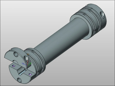
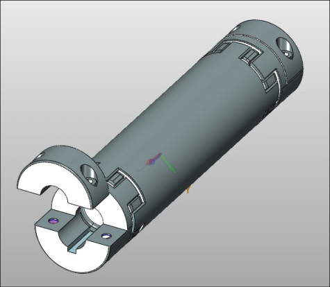
Feature
a and pipe with all-in-one design
b Existing keyway
3 Screw bolts at the end of shaft(x2)
5 Minimize torsion due to assembled
6 Insert double disk(High misalignment
increase in torque by incresing the outside diameter
Minimize torsion
- Level the load, and increase convenience to assemble by bolt it last.
- When inserting couplings on both keyways, the torsion error range is within about 15 degrees.
- When using a reducer, 15 degree/reduction ratio becomes the assembly error range of Load Level.
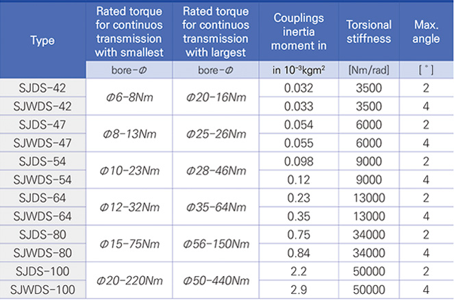
Increase offcenter and angle of deviation endplay by at least 1.5 to 3 times through assemble two double disk couples.
(Listed minimum value in the catalog)
- Remove the clamp, fix the reducer shaft with 2 screws, STS material available.
- Better compensation of both offcenter and angle of deviation, Changable position of keyway
- Minimize tension during assembly. when applied to a narrow space, the position of the shaft end of the reducer can be arranged between b and c.
- Double discs can be used on both sides, in which case offcenter and angle of deviation are allowed more than doubled.